
ADSS Cable Sag and Tension: How to Specify the Right Fittings
Selecting aerial cable fittings by a catalog breaking load alone leaves an important question unanswered: what loads will the installed cable actually place on the fittings?
ADSS cable sag and tension depend on the cable construction, span geometry, temperature and environmental load cases. The anchor clamp, suspension assembly, bracket and pole must be assessed together. This article explains the inputs a buyer or project engineer should collect and why a simplified calculation cannot replace the cable manufacturer’s sag-tension data.
Keep the load definitions separate
- Installation tension: the load experienced during handling and stringing. Observe the cable and installation equipment limits.
- Service tension: the cable tension in a defined installed load case, including the relevant temperature and environmental conditions.
- Allowable working load: a permitted operating load stated under defined conditions. Confirm how the manufacturer defines it.
- Minimum breaking load: a specified minimum failure load under a defined test. It is not a safe operating target.
- Holding or slip performance: the ability of the fitting to retain the specified cable without unacceptable movement or damage.
Ask what each number means before comparing two quotations. A strong metal body does not establish that the complete clamp will grip your cable safely at the required load. Test results should identify the cable or test specimen and the acceptance criteria.
Collect the design inputs first
Provide the cable supplier or responsible designer with the actual route geometry, including span lengths, differences in support height and changes in direction. For each cable, obtain outside diameter, mass per unit length, construction and mechanical data. Required information may also include stiffness, thermal expansion and creep behavior.
Environmental inputs should come from the applicable project rules: design wind conditions, ice where relevant, temperature range, terrain and exposure. Do not select a safety factor from a generic climate label such as coastal or tropical. The design basis determines load combinations, factors and acceptance limits.
Corning publishes product-specific ADSS sag and tension tables that distinguish span and loading conditions. They illustrate why a table for one cable cannot be reused indiscriminately for another.
Why sag changes tension
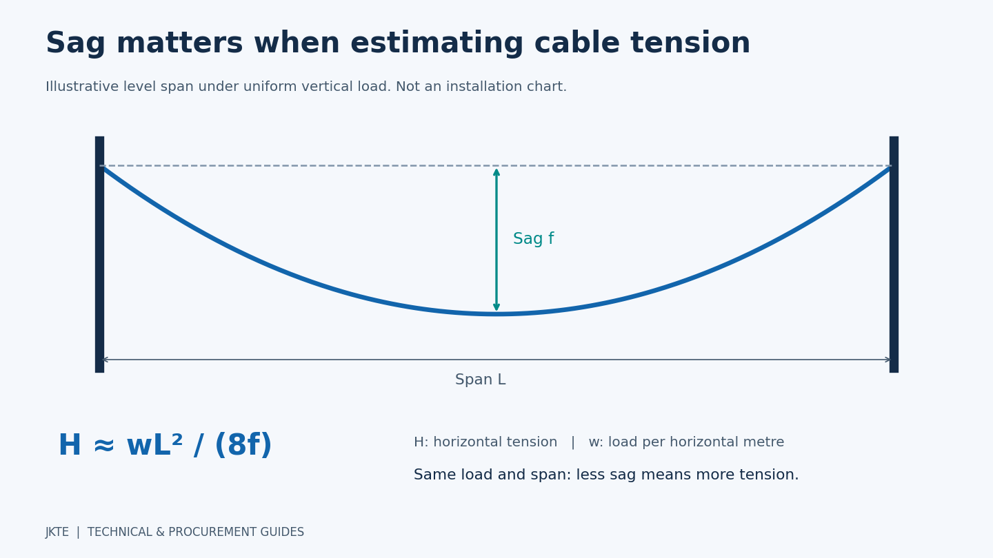
For a level span with a shallow parabolic shape and a uniform vertical load per horizontal metre, a useful educational approximation is:
H ≈ wL2 / (8f)
- H is the horizontal component of tension, in newtons.
- w is the vertical load per horizontal metre, in newtons per metre.
- L is the horizontal span, in metres.
- f is the midspan sag below the support chord, in metres.
The relationship shows why pulling a span tighter can increase tension sharply. It also shows why multiplying cable weight by span length does not, by itself, calculate horizontal tension.
An illustrative calculation
Assume a 50 m level span, a uniform vertical load of 1 N/m and sag of 1 m. The approximation gives H ≈ 312.5 N. If sag is reduced to 0.5 m while the assumed load and span stay the same, H rises to approximately 625 N.
For the same simplified case, the vertical reaction at each end is wL/2, or 25 N. The support tension magnitude is approximately √[H2 + (wL/2)2], giving about 313.5 N in the first case.
These are illustrative values, not installation settings or a clamp recommendation. The example does not solve cable elongation, temperature changes, creep, unequal support levels, wind, ice, dynamic behavior or clearance requirements. Final design requires the approved cable data and engineering method.
Wind, ice and temperature need defined load cases
Wind introduces transverse loading; ice can increase both weight and projected area. These loads have directions and must be combined using the applicable design method. Adding a self-weight tension number to a wind force number is not a valid general calculation.
Temperature and cable elongation affect sag and tension together. The sag used for one temperature and load condition cannot simply be held constant for every other condition. Check the relevant installation, everyday and extreme load cases, as well as required clearances.
Vibration and fatigue are separate concerns from static strength. A fitting that passes a static tensile test may still require a review of bending, vibration and cable-jacket interaction.
Match each fitting to its actual duty
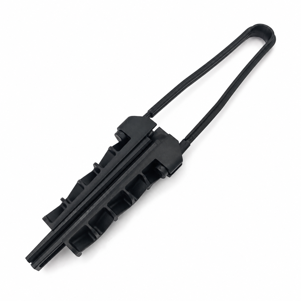
Anchor and dead-end assemblies
These transfer the longitudinal load of the relevant tension section to its support. Verify cable compatibility, holding performance, permissible loading and the complete connection path through the bail, hook, bracket and anchor. A locally stronger part cannot compensate for an underrated connection elsewhere.
Suspension assemblies
An intermediate suspension fitting must accommodate its specified vertical and transverse loads, line angle and any defined longitudinal or unbalanced loads. Do not choose it simply by applying a smaller percentage of the dead-end rating. Check bending and slip behavior against the cable and project requirements.
Brackets and mounting hardware
Consider the actual load direction, lever arm and mounting arrangement. The pole or wall attachment must be suitable for the resulting forces and moments. Use cable brackets and hooks as part of an approved assembly rather than as isolated catalog items.
A useful fitting-selection workflow
- Confirm cable construction and the route’s span geometry.
- Obtain the applicable environmental and clearance requirements.
- Have the cable supplier or designer determine the sag-tension schedule and support loads.
- Match the cable and calculated duties to documented fitting ratings.
- Confirm compatibility tests, installation instructions and acceptance criteria.
- Record approved models and review any substitution before installation.
Keep the calculation revision, cable datasheet and hardware schedule together. If the cable, route, support geometry or design conditions change, review the selection rather than assuming the previous approval still applies.
Frequently asked questions
Can a breaking load be divided by two to obtain the working load?
Not as a universal rule. Use the manufacturer’s stated limits and the project’s required design basis. Different failure modes and test definitions cannot be reduced to one arbitrary factor.
Can the same approach be used for OPGW?
Some mechanical concepts are shared, but OPGW has different construction and additional electrical and grounding considerations. Use OPGW-specific cable data and approved hardware; an ADSS clamp is not automatically interchangeable.
Do calculations need to be repeated every year?
Not routinely just because the calendar changes. Review them when design assumptions, route geometry, cable, exposure or condition change, or when inspection results indicate a problem.
What to send with an ADSS fitting inquiry
Send JKTE the cable datasheet, outside diameter, span schedule, approved support loads, mounting arrangement and quantities. Identify the required load definitions and test criteria. Browse our ADSS anchor clamps and suspension fittings, then request model specifications and a quotation.
Related reading: Spiral vibration dampers for ADSS cable.